A medium-voltage cable must safely carry the load and survive the environment where it is buried. Picking a conductor by current alone is not sufficient.
KiloVolt evaluates XLPE-insulated cables in four arrangements: single-core cables in flat or trefoil formation, and one three-core cable, unarmoured or armoured. Copper is the default, at 20 kV. The ratings are valid only for specific reference conditions — not arbitrary soil or duct installations.
What is MV cable sizing?
An MV cable is chosen to deliver electricity reliably between switchgear, transformers, substations and distribution networks. Cross-section is expressed in mm² and refers to the main phase conductor, not the entire cable diameter.
Before installation, engineers must separately check operating current, thermal capacity, voltage drop, conductor fault withstand, metallic-screen fault duty, insulation voltage class and the physical installation.
What is inside a medium-voltage cable?
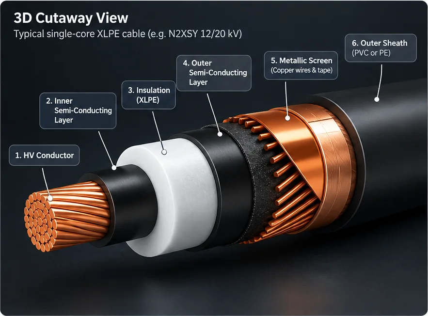
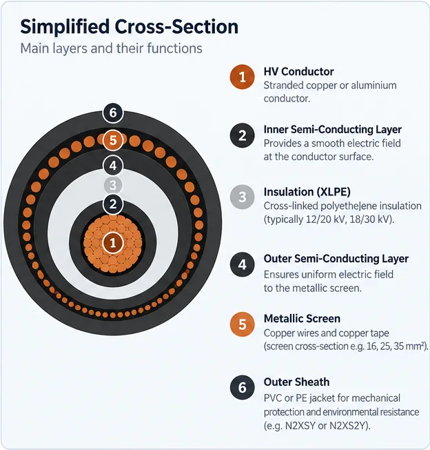
The conductor carries the normal load current. Semiconductive layers smooth the electric field around the insulation. XLPE withstands the electric stress between conductor and metallic screen. The metallic screen provides an intentional earthed boundary and may carry earth-fault current. The oversheath provides external mechanical and environmental protection.
The diagrams illustrate a typical unarmoured single-core XLPE cable. Optional armour, water-blocking layers and manufacturer-specific designs are not shown. Three such single-core cables normally form one three-phase circuit. Example: N2XSY 1 × 150/25 mm² means a 150 mm² copper phase conductor and a separate nominal 25 mm² metallic screen; the screen must be checked against its own fault current and protective clearing time.
What do 6/10, 12/20 and 18/30 kV mean?
Medium-voltage cables are typically marked U₀/U (Uₘ): U₀ is rated conductor-to-earth voltage, U is rated conductor-to-conductor voltage, and Uₘ is the highest system voltage for which equipment is designed. A typical 20 kV system uses a 12/20 (24) kV XLPE cable class, subject to the network's earthing and fault-duration requirements.
The class must be checked separately from cross-section. A cable can carry sufficient current yet be unsuitable for the insulation stress of the network.
Direct buried or in underground ducts?
Direct burial · flat spaced
Underground ducts · flat touching
Direct buried, flat spaced: three single-core cables are laid horizontally with a clearance equal to one cable outside diameter. This is the flat direct-burial reference geometry in IEC 60502-2:2014 Annex B.
In buried ducts, flat touching ducts: each single-core cable is installed in its own air-filled earthenware duct, and the three ducts touch each other. The thermal properties and dimensions of the ducts matter.
Single-core, trefoil: the three single-core cables are grouped in a triangle, either buried directly or one per duct with the three ducts in trefoil. These ratings come from the Prysmian medium-voltage catalogue and are within a few per cent of the flat formation.
One three-core cable: all three phases are in one cable, unarmoured or armoured, buried directly or in a single buried duct. The same section carries less current as a three-core cable, mainly because the three conductors sit close together. For a 35 mm² copper conductor, direct burial: 172 A as single-core cables in flat formation, 153 A as a three-core cable.
Why soil conditions matter so much
Electrical resistance generates heat, approximately proportional to the square of current. XLPE insulation is generally designed around a maximum continuous conductor temperature of 90°C; the surrounding soil must be able to release this heat.
The calculator uses a published reference ampacity subset for 20°C ground temperature, 1.5 K·m/W soil thermal resistivity and 0.8 m burial depth. The ratings are calculated for 6/10 kV cables. A Prysmian catalogue lists the same aluminium ratings for 6/10, 12/20 and 18/30 kV but states that they were calculated for 6/10 kV, so the rating of the actual 12/20 kV product must still be confirmed on its datasheet. The trefoil and three-core ratings come from that catalogue, with the same ground and duct assumptions. The duct reference additionally assumes 1.2 K·m/W thermal resistivity for the earthenware duct and both-end-bonded cable screens.
Warmer soil, dryer soil, deeper burial, nearby loaded circuits, different bonding or other duct materials can reduce the actual permissible current. For those cases use manufacturer data or IEC 60287 calculations instead of applying an arbitrary factor.
From transformer kVA to MV current
In construction, the feeder supplying a transformer is often selected from the transformer’s nameplate apparent power. For a balanced three-phase transformer, the MV rated current depends on the transformer kVA and the line-to-line MV voltage:
When the power is entered in kVA and voltage in kV, the result is directly in amperes. Do not multiply by 1,000 again. You also do not need cos φ because the transformer is already rated in apparent power, not active power.
The result is the rated primary line current at 20 kV and full transformer kVA. For partial loading or several transformers on one MV feeder, use the appropriate design demand instead of blindly assuming a single nameplate rating.
Alternatively, enter the known design current (A) directly. If using MVA, convert using the equivalent formula:
How does a long MV cable lose voltage?
Like an LV feeder, an MV conductor has resistance and inductive reactance. To avoid asking for power factor when sizing a cable from kVA or amperes, the calculator displays a conservative first-order voltage-drop bound:
L is the one-way length in km; R and X are in Ω/km. The usual approximate operating voltage drop is √3 IL(R cos φ + X sin φ), so the magnitude of its resistive/reactive term cannot exceed √(R² + X²). Our bound assumes 90°C-adjusted DC resistance and illustrative reactance, so it is not a prediction of actual voltage drop and does not replace manufacturer AC impedance and a detailed feeder study.
In the table of evaluated sizes, a section whose conservative drop bound reaches the system voltage is shown as “Not feasible” rather than as a percentage above 100 %, and such a section never passes the screening.
At 20 kV the rated MV current is only 28.87 A, while IEC 60502-2 Annex B lists 172 A for a 35 mm² copper single-core model cable directly buried in the specified flat arrangement (a three-core cable of the same section is lower: 153 A). That rating is a thermal reference, not approval of a 35 mm² cable for the installation. For example, 12.5 kA for 1 s requires about 87.4 mm² of copper in our simplified phase-conductor adiabatic screening model, selecting 95 mm² from the current reference-size list. The screen and actual cable rating still require separate verification.
Why a cable must survive short-circuit current
During a fault, current may be thousands of amperes even though the normal load is only a few hundred amperes. The conductor must withstand that heat for the time required by the protective relay and breaker.
For XLPE phase conductors assumed to start at 90°C and reach no more than 250°C, a conservative adiabatic screening factor is k = 143 A·√s/mm² for copper and k = 94 A·√s/mm² for aluminium. The model assumes a single effective RMS fault current for 0.2–5 s. With I in amperes, t in seconds and S in mm²:
Rated load current is only 28.87 A. With an illustrative 10 kA, 1 s phase-fault duty, the copper conductor needs at least 69.93 mm² by the adiabatic formula, so the next size in our data is 70 mm² Cu. If the actual network fault duty is 12.5 kA, 1 s, the requirement becomes 87.41 mm², selecting 95 mm² Cu. A 35 mm² copper XLPE conductor withstands only about 5.01 kA for 1 s under this model.
At 10 kA for 1 s, aluminium needs at least 106.38 mm², selecting 120 mm² from our present table. All these are conductor-only preliminary checks.
Where does 10 kA come from? It is a convenient illustrative setting found in some DEDDIE 20 kV technical specifications—not an actual national average and not necessarily the prospective fault level at the project connection point. For example, the Greek Non-Interconnected Islands Network Code gives a 7.2 kA design figure for 20 kV systems within its scope. Neither number is universally applicable to mainland or island projects. A final calculation must use the prospective three-phase short-circuit current determined for the site (IEC 60909 / network operator data), plus the applicable protection clearing duty including backup protection where relevant. Do not substitute a breaker’s rated breaking capacity for the actual network fault current.
See Prysmian’s technical note on phase-conductor and metallic-screen fault withstand and Schneider Electric’s IEC-based k-factor explanation. The square-root duration scaling and fixed k assumptions are a preliminary thermal screening model, not a complete time-varying I²t or electrodynamic-force calculation.
Why the metallic screen needs a separate fault check
The copper-wire screen surrounds the cable insulation and provides an earthed metallic boundary. Depending on the network and bonding arrangement, it can also form part of the return path for earth-fault current. For instance, a marking such as 1 × 150/25 mm² identifies a 150 mm² phase conductor and a separate 25 mm² nominal copper screen.
Phase-conductor short-circuit withstand and screen earth-fault withstand are two different calculations. A three-phase fault-current value entered for the conductor cannot simply be applied to the screen. The screen may share the return current with other bonded screens, earth conductors, armour and ground, depending on the network configuration.
The manufacturer’s screen construction and short-circuit rating (or validated thermal constant and cross-section), the prospective earth-fault current, the portion expected in each screen, the protection clearing time, and whether the screen is bonded at one or both ends (including any special bonding design).
This is an illustrative adiabatic screening relationship, not a completed screen calculation: the appropriate k value depends on screen construction and allowable temperatures, and the actual current path must be established. In KiloVolt, metallic screen verification remains marked Requires separate study rather than falsely reporting a pass.
250 A, 20 kV, 100 m, copper XLPE
Take a 250 A three-phase design current, 100 m route, direct-buried flat spaced cables, and the exact reference soil conditions. The first reference conductor that carries this normal current, before fault withstand and site verification, is:
A separate practical recommendation requires an additional 15% current capacity:
These results are reference-condition operating-current screening outcomes, intentionally calculated with the fault check omitted to illustrate why ampacity alone is insufficient. The calculator starts with an illustrative 10 kA / 1 s phase-fault assumption, so its minimum will generally be higher. The metallic-screen check remains pending. Final cable parameters and conditions must be verified before procurement. The badges “Reference pass” and “Bound pass” carry that qualification on purpose: they mean the check passed under the stated reference conditions, not that the installed cable is approved.
Mistakes to avoid
Reference buried ampacity is not a universal rating. Soil temperature, resistivity, burial depth and formation all matter.
Duct walls and trapped air change heat dissipation; use the correct reference column and actual duct construction.
The screen has its own construction and earth-fault withstand. Its capacity cannot be inferred from the phase conductor alone.
Precise MV voltage drop needs AC resistance and reactance for the selected cable, formation and screen bonding.
The same section carries less current as one three-core cable. Select the arrangement that is actually installed.
A generic IEC-based model rating is not a verified current-carrying capacity for every cable brand and sheath design.
Standards and source data
These sources explain the reference data and limits of the calculation. Consult the applicable official standards and actual cable manufacturer for final engineering design.
Official IEC publication → · Public copper reference table →
Prysmian short-circuit technical note → · IEC-based conductor k factors →
Current ratings for all four arrangements → (a distributor-hosted copy; the edition is not stated)
IEC 60502-2:2014 reference tables are used as a limited numerical dataset. The current consolidated IEC edition includes amendments and corrigenda, so check the data against the current edition before relying on it.