A device that compares two currents
A residual current device (RCD) opens a circuit when some of the current leaves it through a path it should not take, for example through a person or through damaged insulation to earth. This guide shows how it senses that, what its ratings mean and where its limits are.
This is educational material. The requirements that apply to an installation come from the standards and national rules in force and from the manufacturer’s data.
What an RCD does
In a healthy circuit the current that goes out through the line conductor comes back through the neutral. The two are equal and opposite. If part of the current finds a path to earth, the neutral carries less than the line. The RCD adds the currents of all the live conductors that pass through it. The sum should be zero. When it is not, the difference is the residual current IΔ, and the device opens if IΔ exceeds its rating.
Two things follow. An RCD does not measure how large the load current is, so it does not protect against overload or short circuit between live conductors. And a person who touches line and neutral at the same time carries a current that returns through the neutral, so the RCD sees no difference and does not trip.
Inside an RCD
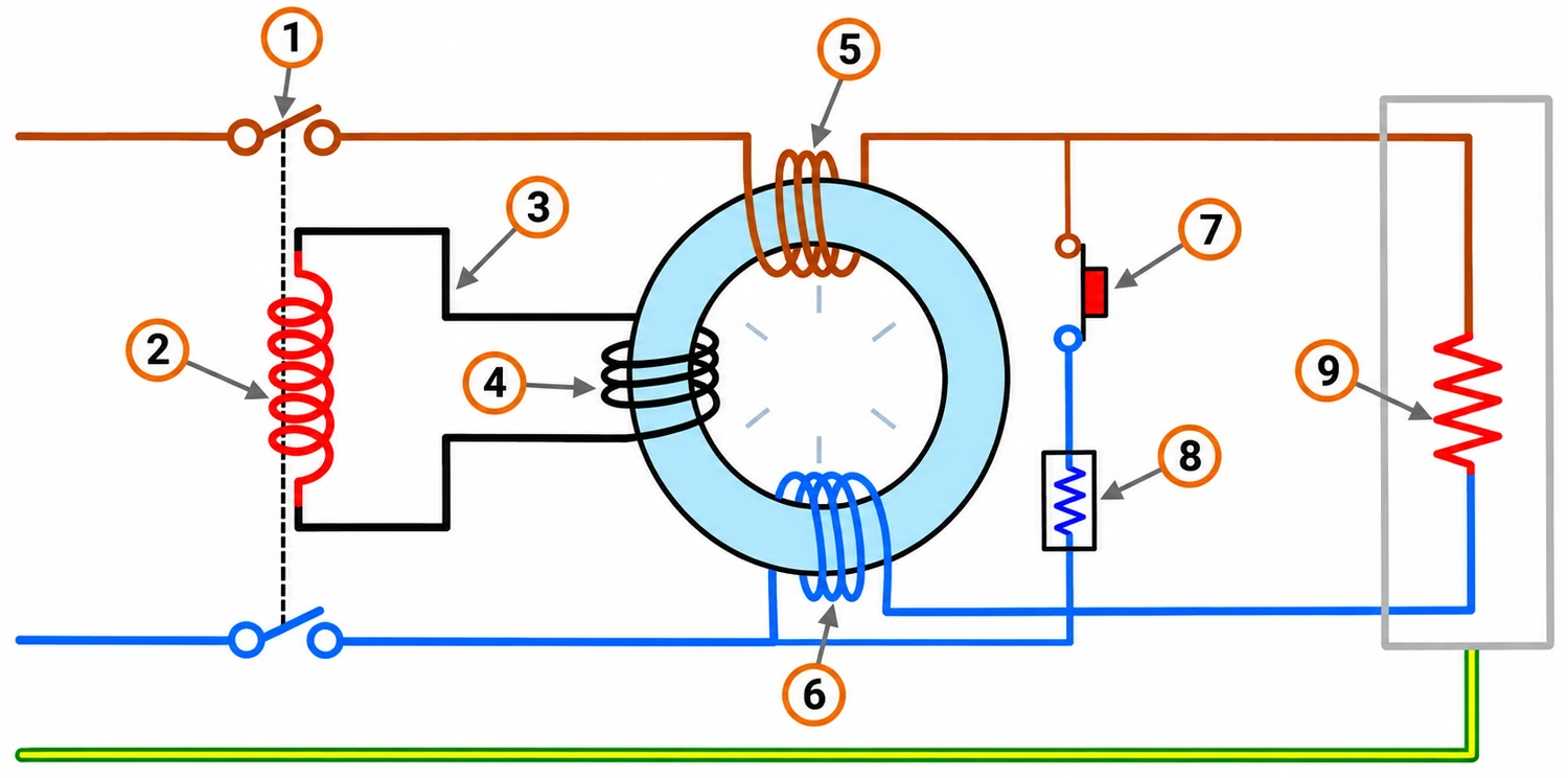
- Main contacts
- Trip coil
- Sensing circuit
- Sensing coil
- Main coil (phase)
- Neutral coil
- TEST button
- Test resistor
- Load
- Ring-shaped core: the line and neutral conductors pass through it. It works as a current transformer: balanced currents cancel, a residual current magnetises it.
- Sensing winding: a coil on the core. A residual current induces a voltage in it.
- Release: a relay that receives the signal and unlatches the mechanism. In some designs the signal is strong enough to act on it directly. Others amplify it electronically and need the line voltage to do so; the manufacturer’s data says which.
- Mechanism and contacts: when unlatched, a spring opens the main contacts in all the poles. The handle shows the state and re-closes the device by hand.
- TEST button: passes a small current through a resistor around the core, which creates a real imbalance. If the device opens, the sensing, the release and the mechanism work. It does not prove that the installation is earthed.
Ratings and trip times
The rated residual operating current IΔn is the leakage at which the device is designed to trip. Standard values include 10, 30, 100, 300, 500 and 1000 mA. A device is allowed to trip anywhere between half of IΔn and IΔn, and must not trip below half of it. Its trip time must stay under the limit for its type.
| Rated IΔn | Typical use |
|---|---|
| 10 to 30 mA | High sensitivity. Additional protection of people against shock, in particular against direct contact. |
| 100 to 300 mA | Protection against earth-fault currents that can start a fire, and a time-delayed device upstream of 30 mA devices. |
| 500 to 1000 mA | Low sensitivity. Protection of equipment and installations, not of people. |
Maximum break time for a general-purpose device, from the product standards: 300 ms at IΔn, 150 ms at 2 × IΔn and 40 ms at 5 × IΔn. A selective device, marked S, is deliberately delayed so that a 30 mA device downstream trips first: it takes between 130 and 500 ms at IΔn, so it does not open during a brief fault that a downstream device clears.
Types AC, A, F and B
The type tells which waveform of residual current the device detects. Modern equipment rectifies the supply, so the leakage current is not always a clean sine wave.
| Type | Detects | Typical loads |
|---|---|---|
| AC | Sinusoidal residual current only | Resistive and other linear loads |
| A | AC and pulsating DC | Single-phase loads with rectifiers or thyristor control, such as electronic equipment and hobs |
| F | Type A currents and composite multi-frequency currents | Single-phase equipment with a variable-speed drive, such as air conditioners and washing machines |
| B | Type F currents and smooth DC | Three-phase rectifiers and variable-speed drives, photovoltaic inverters and EV charging, depending on the equipment manufacturer’s requirement |
A smooth DC residual current can saturate the core of a type AC or A device and stop it from tripping at all, which is why the equipment manufacturer’s instructions say which type is needed upstream. A type A device is only designed to tolerate a few milliamps of smooth DC, typically 6 mA.
RCCB, RCBO and MCB
- RCCB: residual current circuit-breaker without overcurrent protection. It reacts only to leakage, so a miniature circuit-breaker (MCB) or fuse must protect the circuits against overload and short circuit.
- RCBO: an RCD and an MCB in one device. It trips on leakage, overload and short circuit, and protects one circuit.
- MCB: overload and short-circuit protection only. It does not detect leakage.
One RCCB can serve a group of circuits, and a leakage on any of them opens the whole group. An RCBO on each circuit isolates only the circuit with the fault and avoids nuisance trips from the leakage of other circuits adding together.
Where it is used and why it trips
IEC 60364-4-41 (HD 60364-4-41:2017, clause 411.3.3), which in Greece is part of ΕΛΟΤ 60364, requires additional protection by a 30 mA RCD for AC final circuits that supply socket-outlets rated up to 32 A and for mobile equipment rated up to 32 A used outdoors, with the exceptions the standard allows. Other parts of the series add 30 mA protection for special locations such as bathrooms. In Greece, Υ.Α. 130414/2019 goes further: it requires RCDs of 30 mA or less on the final circuits within its scope, with the exceptions it lists, such as circuits where an RCD is not permitted. The edition and the national rules in force decide the exact scope for an installation.
The usual reasons an RCD trips without a fault being obvious:
- Leakage that adds up. Every class I appliance with a filter leaks a few milliamps to earth in normal operation, and the leakage of all the appliances on one RCD adds.
- Moisture or damaged insulation in a cable, a socket, a heater or a pump.
- A neutral that touches earth downstream of the RCD, or a neutral shared with a circuit on another RCD, so that part of the neutral current bypasses the core.
- Surges, for example from lightning or switching, in an RCD that is not rated to ride through them.
Press the TEST button regularly, for example every month, and follow the manufacturer’s instructions.
Worked example
Eight office computers, each with a normal leakage of 3 mA to earth through its filter, are on one 30 mA RCD. The normal leakage is 8 × 3 mA = 24 mA. The device must not trip below 0.5 × 30 = 15 mA, so 24 mA is within the range where tripping is permitted. Reliable operation cannot be assumed, and small changes in the leakage may cause trips.
A common rule of thumb keeps the normal leakage below about one third of IΔn, which is 10 mA for a 30 mA device. Spread over three devices, with 3, 3 and 2 computers, the leakage is 9, 9 and 6 mA, all below that limit.
The earth-fault path also matters for protection. See the PE conductor guide and the earth-fault chapter of the LV short-circuit guide.