A switch that opens itself
A miniature circuit-breaker (MCB) opens by itself when the current in a circuit is too high, and can be closed again by hand. It protects the cable and the equipment behind it. This guide shows what is inside, how it senses overload and short circuit, how it puts out the arc and how to pick the rating and the curve.
This is educational material. The requirements that apply to an installation come from the standards and national rules in force and from the manufacturer’s data.
What an MCB does
An MCB protects against two different conditions. An overload is a current somewhat above the rating that lasts long enough to overheat the conductors. A short circuit is a very large current caused by a fault of very low impedance between live conductors, or between a live conductor and earth in a TN system.
Household and similar MCBs are covered by IEC 60898-1 (EN 60898-1). Circuit-breakers for industrial use are covered by IEC 60947-2. An MCB does not detect leakage to earth: that is the job of a residual current device, described in the RCD guide.
Inside an MCB
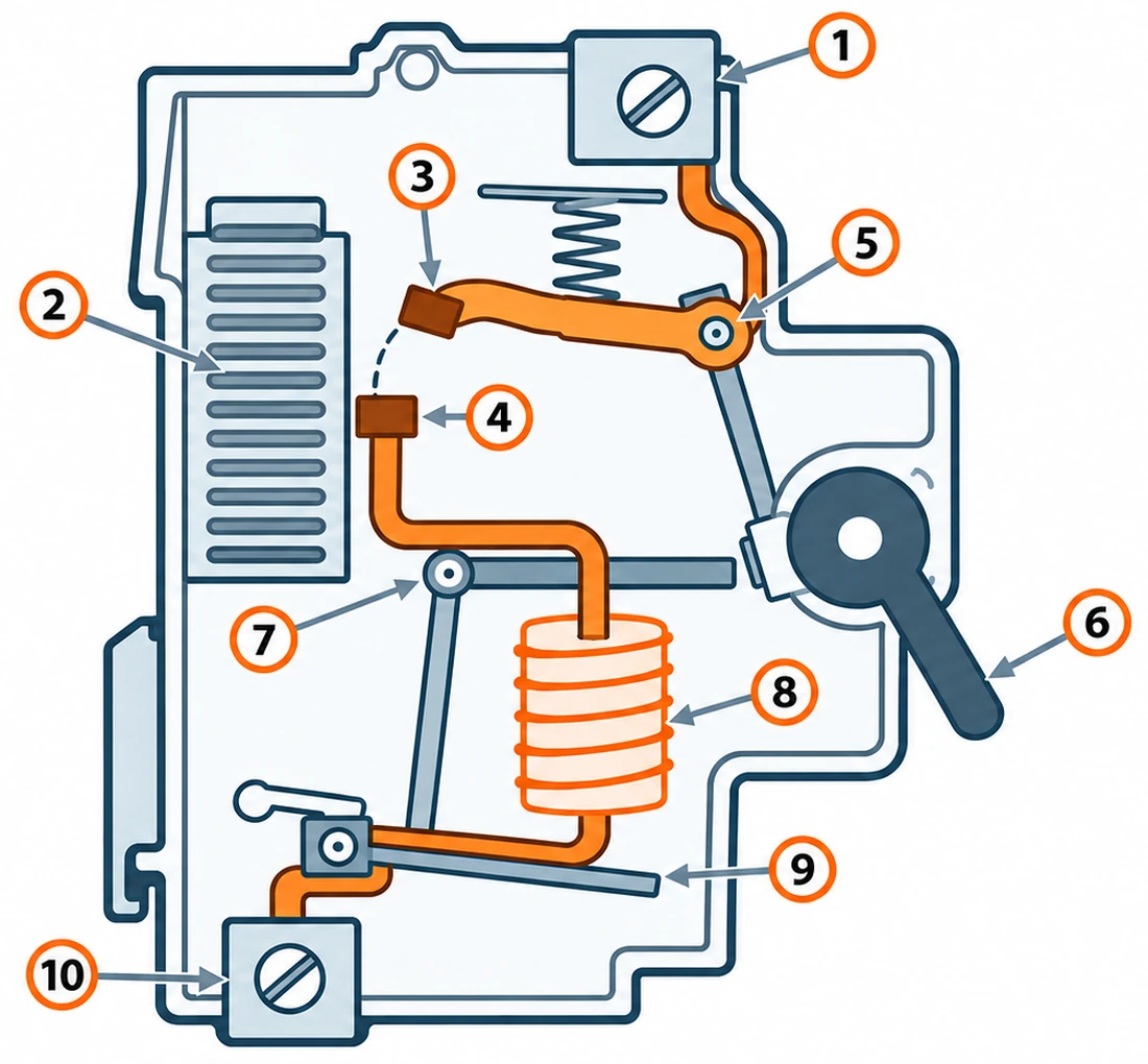
- Line terminal
- Arc chute (splitter plates)
- Moving contact on its arm
- Fixed contact
- Pivot of the moving arm
- Handle
- Trip bar
- Coil (magnetic trip)
- Bimetal strip (thermal trip)
- Load terminal
- Coil and plunger: the load current flows through the coil. A short-circuit current magnetises it strongly enough to pull in the plunger, which strikes the latch. This is the magnetic trip.
- Bimetal strip: two metals bonded together that expand by different amounts. The load current heats the strip and it bends. If the current stays high, it bends far enough to push the latch. This is the thermal trip.
- Latch and mechanism: hold the contacts closed against a spring. The mechanism is trip-free: the contacts open even if the handle is held in the ON position.
- Contacts and arc chute: the contacts carry the current. The arc chute, a stack of steel plates, puts out the arc that forms when they open under current.
Thermal and magnetic trip
The thermal element has an inverse-time characteristic: the larger the overload, the sooner it trips. For an MCB to IEC 60898-1 the conventional non-tripping current is 1.13 × In and the conventional tripping current is 1.45 × In, with a conventional time of 1 hour for rated currents up to 63 A and 2 hours above that.
The magnetic element has no intentional delay. At the upper limit of its range the standard requires it to trip within 0.1 seconds, and in practice it is much faster.
The thermal element reacts to temperature. An MCB in a hot enclosure, or mounted tightly next to other devices that give off heat, may trip at a lower current than its rating. Manufacturers publish correction factors for this.
Putting out the arc
When the contacts open under current, the current does not stop at once: it keeps flowing through the air between them as a very hot arc. The device must put it out, and a short-circuit current can be thousands of amperes.
Magnetic forces and the shape of the contacts and arc horns push the arc into the arc chute. The steel plates split it into many short arcs in series. Each short arc adds a voltage drop, and together they exceed the supply voltage, so the current falls to zero and does not restart.
The rated short-circuit capacity Icn is the largest prospective short-circuit current the MCB can interrupt. Common values for household MCBs are 4.5 kA, 6 kA and 10 kA. It must be at least equal to the prospective short-circuit current at the place where the MCB is installed. See the LV short-circuit guide.
Curves B, C and D
The letter is the type of the instantaneous trip. It tells at what multiple of the rated current In the magnetic element operates. The thermal part is the same for all of them.
| Curve | Magnetic trip | Typical use |
|---|---|---|
| B | 3 to 5 × In | Resistive loads and general circuits, and long cable runs where the short-circuit current is low |
| C | 5 to 10 × In | General purpose: lighting, mixed loads and motors with a moderate starting current |
| D | 10 to 20 × In | Loads with a high inrush current, such as transformers and some motors and welding equipment |
A higher curve is not simply safer. A curve that is too low trips at switch-on of a transformer or a motor. A curve that is too high may not trip magnetically on a fault at the end of a long cable, where the fault current is small: the MCB then relies on the slow thermal element, and the fault stays on far too long. Other curves exist, mainly for industrial breakers, so check the data sheet.
Choosing an MCB
- Rated current In: common values are 6, 10, 16, 20, 25, 32, 40, 50 and 63 A. It must be at least the design current Ib and no more than the cable’s current-carrying capacity Iz.
- Conventional tripping current: IEC 60364-4-43 also asks that the current that makes the device operate, I2, does not exceed 1.45 × Iz. For an MCB to IEC 60898-1, I2 is 1.45 × In, so this is met when In ≤ Iz.
- Curve: high enough to ride through the inrush of the load, and low enough that the magnetic trip operates on the smallest fault current of the circuit.
- Breaking capacity: Icn at least equal to the prospective short-circuit current at the MCB.
- Poles and voltage: one, two, three or four poles, rated for the system voltage, for example 230/400 V.
To protect against earth faults and shock in a TN system, the fault current at the farthest point must be high enough to make the device operate within the required time. For an MCB the current that surely trips it is the upper limit of its magnetic range: 5 × In for B, 10 × In for C and 20 × In for D. The requirement is written Ia ≤ U0/Zs, where Zs is the earth-fault loop impedance and U0 the line-to-earth voltage. See the LV cable sizing guide and the PE conductor guide.
Worked example
A 230 V single-phase circuit carries a design current Ib = 14 A. The cable has a current-carrying capacity Iz = 20 A. The rated current must satisfy 14 ≤ In ≤ 20, so the next standard size, In = 16 A, fits. The conventional tripping current is I2 = 1.45 × 16 = 23.2 A, which is below 1.45 × 20 = 29 A.
The measured earth-fault loop impedance at the farthest socket is Zs = 1.2 Ω. The earth-fault current is 230 / 1.2 ≈ 192 A. The upper limit of the magnetic range of a 16 A device is 5 × 16 = 80 A for B, 10 × 16 = 160 A for C and 20 × 16 = 320 A for D.
The fault current of 192 A is above 80 A and above 160 A, so a B16 or a C16 trips magnetically. It is below 320 A, so a D16 may not: it would rely on the thermal element, which is too slow. The curve matters as much as the rated current.